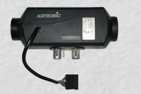


|
Identifier code |
Loom Wire colour |
|
|
a1 |
Thin red |
+12 volts power to controller |
|
a2 |
Yellow |
Switch on signal from controller, (+12v = On, 0v = off) |
|
a7 |
Grey/red |
Set target temperature from controller |
|
a8 |
Brown/white |
Reference earth to controller (0 volts) |
|
a6 |
Blue / white |
Diagnostics signals, (serial data) only used by some controllers and test equipment |
|
a3 |
Grey |
External temperature sensor - |
|
|
Thin brown |
0 volts power (aka earth or negative supply) Usually only used as negative wire for indicator lights |
|
Identifier code |
Pin |
Wire colour |
|
|
a1 |
1 |
Red |
+12 volts power |
|
|
2 |
|
|
|
|
3 |
|
|
|
a2 |
4 |
Yellow |
Switch on signal from controller, (+12v = On, 0v = off) |
|
|
5 |
Green/red |
Pulsed output to fuel metering pump |
|
a8 |
6 |
Brown/white * |
Reference earth to controller (0 volts) |
|
a7 |
7 |
Grey/red |
Set target temperature input, from controller |
|
a6 |
8 |
Blue/white |
Diagnostics signals, (serial data) |
|
|
9 |
|
|
|
|
10 |
Brown |
0 volts power (aka Earth or negative supply) |
|
|
11 |
|
|
|
a3 |
12 |
Grey |
External temperature sensor input - |
|
|
13 |
Blue |
ADR (Hazardous goods) - |
|
|
14 |
Blue/black |
ADR (Hazardous goods) - |
|
|
15 |
Pink |
Car alarm - |
|
|
16 |
Black/green |
Output for external fan - |
|
Identifier code |
Pin |
Wire colour |
|
|
|
1 |
Red thick |
+12 volts power input from battery via 20 Amp fuse |
|
|
1 |
Red |
+12v input from ignition switch or battery via 5 Amp fuse , only fitted on some looms |
|
a1 |
1 |
Red thin |
+12 volts output to controller |
|
|
2 |
|
|
|
|
3 |
|
|
|
a2 |
4 |
Yellow |
Switch on signal from controller, (+12v = On, 0v = off) |
|
|
5 |
Green/red |
Pulsed output to fuel metering pump |
|
a8 |
6 |
Brown/white |
Reference earth to controller (0 volts) |
|
a7 |
7 |
Grey/red |
Set target temperature input, from controller |
|
a6 |
8 |
Blue/white |
Diagnostics signals, (serial data), used by some controllers |
|
|
9 |
|
|
|
|
10 |
Brown thick |
Negative power input from battery (aka earth, ground, or 0 volts) |
|
|
10 |
Brown |
Negative power to fuel metering pump |
|
|
10 |
Brown thin |
Negative power (usually not used with most controllers) |
|
|
11 |
|
|
|
a3 |
12 |
Grey |
External temperature sensor input - |
|
|
13 |
Blue |
Usually not used |
|
|
14 |
Blue/black |
Usually not used |
|
|
15 |
Pink |
Usually not used |
|
|
16 |
Black/green |
Usually not used |
|
Identifier code |
ECU Pin |
Wire colour |
|
|
|
1 |
|
? |
|
|
2 |
White/red |
? |
|
|
3 |
Green/red |
Pulsed output to fuel metering pump |
|
a6 |
4 |
Blue/white |
Diagnostics signals, (serial data), used by some controllers |
|
|
5 |
Red thick |
+12 volts power input from battery, (fused at 20 Amps round ceramic, or 30 amp flat blade fuses) |
|
a1 |
5 |
Red thin |
+12 volts output to controller |
|
|
6 |
|
|
|
a7 |
7 |
Grey/red |
Set target temperature input, from controller |
|
a3 |
8 |
Grey |
External temperature sensor input - |
|
|
9 |
White |
Glowpin |
|
|
10 |
|
|
|
|
11 |
Brown thick |
Negative power input from battery (aka earth, ground, or 0 volts) |
|
|
11 |
Brown |
Negative power to fuel metering pump |
|
|
11 |
Brown thick |
Glowpin |
|
|
11 |
Brown thin |
Negative power (usually not used with most controllers) |
|
|
12 |
|
|
|
a8 |
13 |
Brown/white |
Reference earth to controller (0 volts) |
|
a2 |
14 |
|
Switch on input from controller, (heater on +12 volts, heater off 0 volts) |

